Continuous Casting System Stopper
Continuous Casting System Stopper description
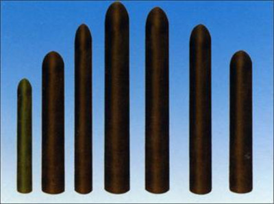
Continuous casting system stopper is installed above tapping nozzle. Through adjusting the gap between stopper and nozzle, steel liquid flowing speed can be controlled. The earliest sleeve bricks of stopper are high alumina bricks or clay bricks. Stopper end is made by alumina carbon refractory. They need to assemble with steel structural controlling rod for using. The service life of combined stopper is not very high, usually less than 6 hours. The main damage reasons of stopper are: On one hand, steel structure is softened in long term high temperature environment and loses controlling effect, on the other hand, sleeve brick is corroded too quickly. To solve this problem, steel controlling rod should have good high temperature performance, sleeve brick should have excellent corrosion resistance and stopper end should properly match with nozzle bowl part.
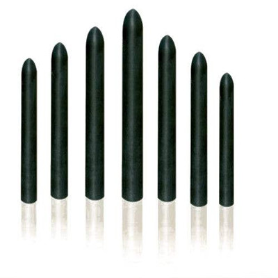
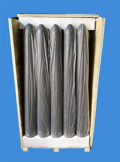
Another method to solve the problem of combined stopper’s low service life is adopting integral stopper, i.e., alumina carbon integral stopper. Alumina carbon integral stopper is made by isostatic pressing molding, solidifying, mechanical processing and carbonizing, there is no metal rod in alumina carbon stopper and avoids the problem of metal rod softening. The service life of alumina carbon integral stopper can reach to 10h. But stopper end and nozzle bowl part will be scoured irregular and not smooth, it will cause difficulty for flow speed control, or even can’t close. That is key factor constraining the service life of alumina carbon stopper.
Continuous Casting System Stopper Physiochemical Index
| Item | Chemical composition (w %) | Cold CS/Mpa ≥ | Apparent porosity % ≤ | High Temp. rupture strength Mpa | Thermal shock resistance /times | |||||
| Al2O3 ≥ | C≥ | ZrO2 | SiO2 | MgO | ||||||
| Integral stopper | 60 | 25 | / | / | / | 16 | 19 | ≥5 | ≥5 | |
| 55 | 23 | / | / | / | 15 | / | ≥4 | ≥5 | ||
| Combined stopper | Sleeve brick | 60 | / | / | ≤30 | / | 40 | 18 | / | ≥20 |
| Sleeve brick | 42 | / | / | ≤52 | / | 40 | 18 | / | ≥20 | |
| Stopper end | 80 | 10 | / | / | / | 40 | 18 | ≥12 | / | |
| Stopper end | 75 | 10 | ≥6~9 | / | / | 40 | 6 | ≥12 | / | |
| Composite stopper | Main body | 60 | 25 | / | / | / | 16 | 19 | ≥5 | ≥5 |
| Slag line | / | 14 | / | / | 80 | 30 | 5 | ≥10 | / | |
| Slag line | 75 | 10 | ≥6~9 | / | / | 25 | 10 | ≥8 | / | |
| End | / | 5 | ≥90 | / | / | / | / | / | / | |
| End | 85 | 5 | / | / | / | / | / | / | / | |
Continuous Casting System Stopper applications
For steel mills using converter to produce ordinary construction steel , steel liquid supply is sufficient, it needs the long service life of stopper, the longer the better. For steel mills producing special steel, different types of steel have different corrosion to stopper, so stoppers which can resist different kinds of steel liquid corrosion is needed. For this reason, slag line part of stopper adopts magnesia carbon refractory, stopper end part adopts alumina zirconia carbon refractory.
